|
Russell's Bourke 30 Explained In Simple Terms
Care
of Hot Rod Magazine, 1954.
Excerpted from the authentic original Bourke Engine Documentary,
pages 111 thru 114, sold by Bourke-Engine.Com
Original author of this article, George Hill, calls the Bourke
engine a 2-stroke. It is not a 2-stroke engine.
It is
a 1 stroke engine taking care of all 4 cycles in one stroke 2 times per
revolution!
Edited
and reformatted for clarity and content by David Wolfe, Founder,
Bourke-Engine.Com.
Free
to copy, share and distribute as long as you refer to www.Bourke-Engine.Com as the
originator and give credit to Russell Bourke and the editor.
Also,
check out www.projectbourke.com
for lots of current pictures and video clips on this remarkable little
powerhouse! Updated regularly! |
|
This is an era of new engines. We are quite sure this is true for we
read all about the revolutionary new engine designs in advertisements
everywhere and listen intently as radio and TV personalities explain the
remarkable engineering advancements contained in our present day
automobile engines. Much has been accomplished in the past few years by
beefing up the lower ends, converting to overhead valves, shortening the
stroke to reduce piston speed and converting to complex four-throat
carburetors.
The basic design, however, has been unchanged for over
50 years. Even longer than that if we care to go way back to the late
1800’s or early 1900’s when our successful racing engines of today were
first put on paper. Designers and engineers of that period knew how to lay
out an efficient engine comparable with our best of today, but alas, they
were not blessed with the metallurgical advancements used freely in our
present day engine laboratories. Their designs were forced to remain on
the drawing board until metals were produced that could withstand the
tremendous stresses and strains developed in high output four-stroke
engines.
Perhaps we are now ready for the Bourke engine, or better
yet, now that we have hopped up every Detroit engine to the point of
self-destruction, the Bourke engine is now ready for us. It may not be the
last word in design, for all designs will forever be improved upon, but at
least it is a step in the right direction.
Russell Bourke, of
Portland, Oregon, sole inventor and designer of this new engine, has long
sought an answer to the wasted energies and to the reduction of stresses
and strains in the conventional engine. It all began back in 1918 when
Bourke was teaching engine theory and maintenance in the Air Service
School at Kelly Field, Texas. Endless discussions with other instructors
and students soon convinced Bourke that much was left to be desired in the
internal combustion engine using the Otto cycle. Heavy, inefficient and
employing too many precision parts, they would one day become as extinct
as the stream-powered car.
For fourteen years Russell studied the
problems and in 1932 came up with a new engine and his first working
model. This first engine was basically successful but there was room for
many refinements. In 1938 Bourke built a four cylinder radial to be tested
for outboard marine use. This engine literally put itself back on the
shelf. It had too much torque for existing drives. A less powerful two
cylinder opposed unit was then built and it proved successful after 2000
hours of testing in a boat.

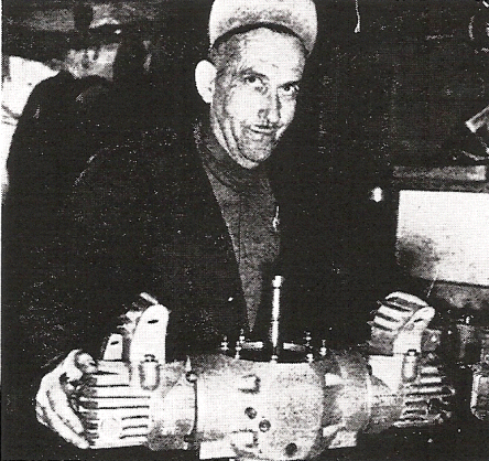
Check that "foxy"
look as Bourke muses, "Look what I have here!" Engine can be expanded in
multiples of two cylinder units to equal larger displacements, i.e.,
2-4-6-8 cylinders and so on. |
|
All the lost
energies present in the four-stroke engine have been put to work. Like a
Judo expert that makes use of his adversary’s strength and momentum.
Bourke had made every lost motion in the engine perform a needed
operation.
The engine and its functions are simplicity exemplified,
yet the engineering and development involved are by no means simple. It is
of the opposed cylinder, two-stroke type. Russell calls it a "mono-stroke
engine". Indeed it is by it's construction and operation. Co-operative
pistons are connected to one rigid connecting rod that shuttles through an
oil filled, crankcase sealed off from the cylinders hence, no oil changes
needed.. There is no blow by introduced into the crankcase to pollute the
oil. There are only two moving parts in the engine: 1-The
piston-connecting-rod- yoke assembly; 2-The crankshaft. All other parts
usually found in the conventional engine have been discarded.
There
is no flywheel as the crankshaft is dynamically balanced for all speeds
and is not connected solidly with the piston rod assembly. Operated
through a streamlined, high speed version of the “Scotch-Yoke,” all
kinetic and inertial forces generated by the piston rod assembly are used
directly for charging and compression.
The forces delivered to the
crankshaft are then one-directional and permit a greater power output with
almost instantaneous acceleration under load.
Before we
attempt to follow the pistons through a complete crank revolution, let us
take a close look at the parts involved.
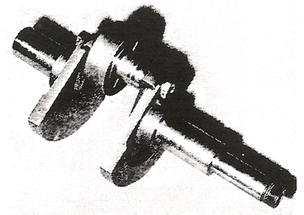
THE
CRANKSHAFT
This counter-balanced unit, below, supported
at each end in double row ball bearings, has only one crankpin and on it
is mounted a three-in-one or triple slipper bearing. The inner split (hub)
ring turns freely on the crankpin and serves as a seat and speed reducer
for the middle or intermediate ring. The outer ring serves as contact
point with the rod assembly and through it all energy generated by the
pistons is transmitted to the crankshaft, free to ride up and down in the
yoke (center of the piston rod assembly) and so develops the rotational
action of the crankshaft. The crank can be turned either direction so that
the engine can be run clockwise or counterclockwise at will. The direction
of the rotation is governed by the timing of the ignition system.

PISTON-ROD-YOKE
ASSEMBLY
The piston-rod
assembly is made up of two machined plates that form the yoke, two rod
extensions, two pistons with pins that fix them into permanent position
(they do not swivel or turn on the piston as in conventional engines), and
two rings on each piston. The two rod extensions are guided through
pressure sealed bushings in the cylinder base of the
crankcase.

The piston-rod-yoke
assembly is one of the two moving parts of the Bourke engine. The
three-in-one bearing on the crankpin, above, slides up and down in the
machined yoke. The slot in the side of the piston allows the new air/fuel
charge to begin its escape into the transfer jacket, thus allowing a
smoother flow, without pulsation.
(Continued on page 2) |


